MasterKey: Concrete Slab and Wall Design
NEW - Automated Concrete Wall Design in finite element frames

- Overview
- Slab Reinforcement Design
- Wall Reinforcement Design
- Long-Term Slab Deflection
- Design Codes
- Output
The MasterSeries 2023 release now includes the design of FE Shear Walls as part of our Concrete Slab Design Module, which has now been renamed to MasterKey: Concrete Slab and Wall Design.
MasterFrame and Finite Element Analysis
MasterKey: Concrete Slab and Wall Design is considered an add-on module.
MasterFrame and MasterFrame: Finite Element Analysis are also required, for the FEM based design of Concrete Slabs and Shear Walls to EC2 (Eurocode 2) alongside MasterKey: Concrete Slab and Wall Design.

These Analysis and Design Modules can come individually, as bundles or can be incorporated into our very popular; PowerPad and Building Design Suites.
Your 3d Frame and all its Geometric and Material Properties, plus loading can be setup and analysed within MasterFrame's FE Analysis Module, then designed using the integrated Concrete Slab and Wall Design.
Once this analysis has been carried out, the slabs and walls can be designed in our Concrete Slab and Wall Design module.
MasterKey: Concrete Slab and Wall Design
With the updated MasterKey: Concrete Slab and Wall Design module, the specification and design of longitudinal and shear reinforcement in slabs and walls is now an easy process, allowing you to interactively identify and resolve any failure areas.
Our software allows you to design to Eurocode, British Standard and South African codes. Concrete Shear Walls are designed only to Eurocode.

"For many years, AL Alia Structural Engineers have been using the Masterseries Software to design a different types of steel, timber and Concrete structures, Lately we have purchased the latest Concrete FE Slab design which we can confirm that it's very powerful and friendly. Rebar design is now a fast, simple and logical process."
AL Alia Trading & Contracting Management
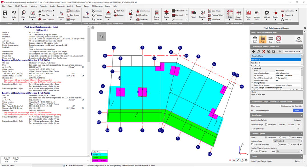
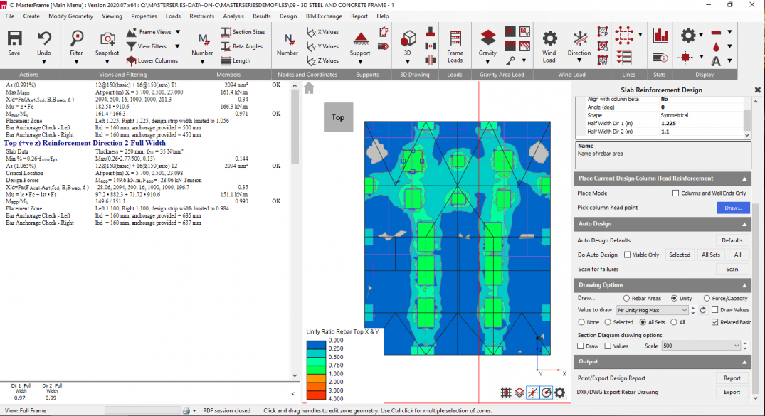
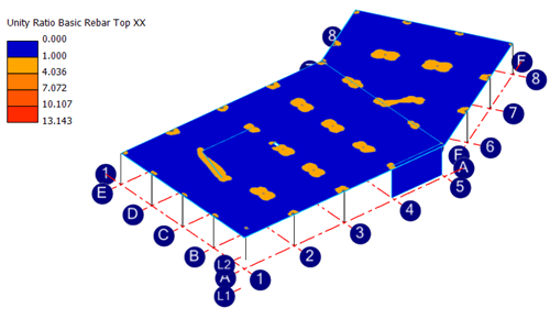
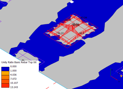
Longitudinal Slab Reinforcement
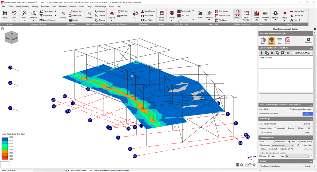
The basic premise is to provide a consistent background of basic reinforcement throughout, and then add additional reinforcement if required. The graphical unity ratios below clearly show the failing zones of the slab, where additional reinforcement need to be placed.
When carrying out a Concrete Slab Design we can get specify two types of additional reinforcements:
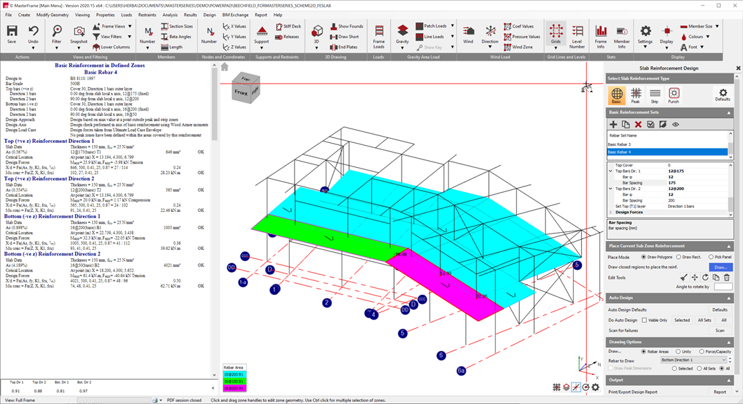
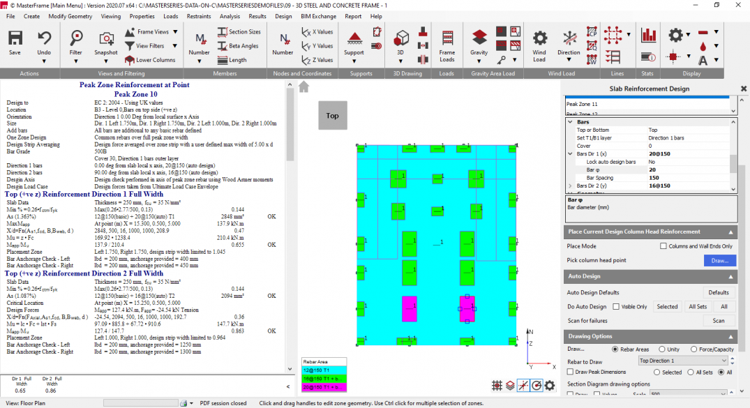
- Peak reinforcement: can be placed over a point (for example column head, wall end or point load). Peak reinforcement zone contains two sets of orthogonal bars (shown below)
- Strip reinforcement: similar to the Peak reinforcement, but only has reinforcement in one direction (parallel or perpendicular to the centerline of the reinforcement zone). Can be placed with drawing the centerline of the strip
The Auto Design function can find, not just the most economical reinforcement solution (bar sizes and spacing) but is also able to optimise the size of the additional reinforcement zones. The below design is using inner & outer peak strips to reduce the rebar used.

Punching Shear Design
Punching shear design check can be placed on column heads, wall ends and corners.
The design check automatically identifies the position (internal or external), the column/wall shape etc. and determines the punching shear parameters.

If punching shear reinforcement is required, the design automatically creates the reinforcement arrangement based on the selected rebar layout.
MasterKey: Concrete Slab and Wall Design offers four types of rebar layout:
- Equally spaced on perimeter
- Radial layout
- Even grid
- Cruciform for support face
New to MasterSeries 2023 is the introduction of the Concrete Shear Wall Design to the Concrete Slab Design module.
The Shear Wall module similarly relies on MasterFrame: Finite Element Analysis Software to produce Finite Element Surfaces, for analysis to be carried out within MasterFrame. Once carried out the Walls can be designed within MasterKey: Concrete Wall Design.
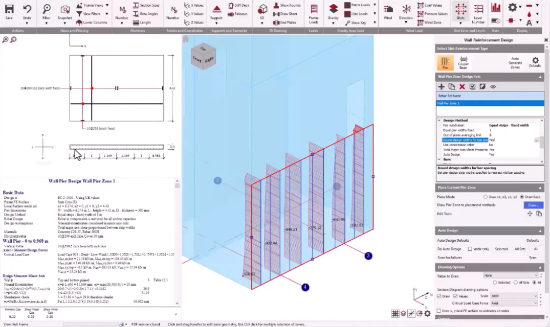
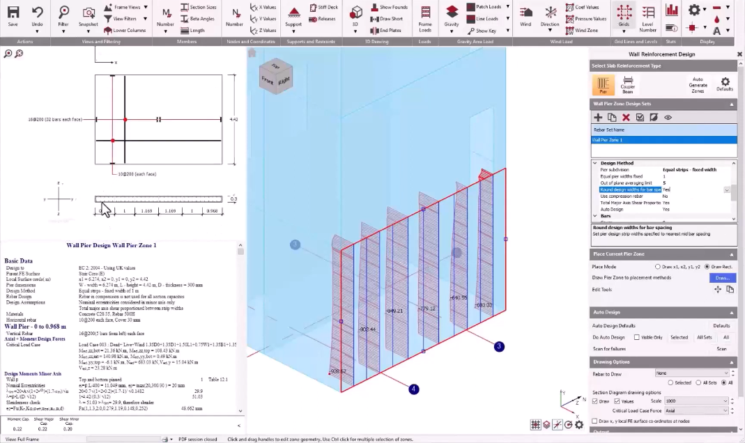
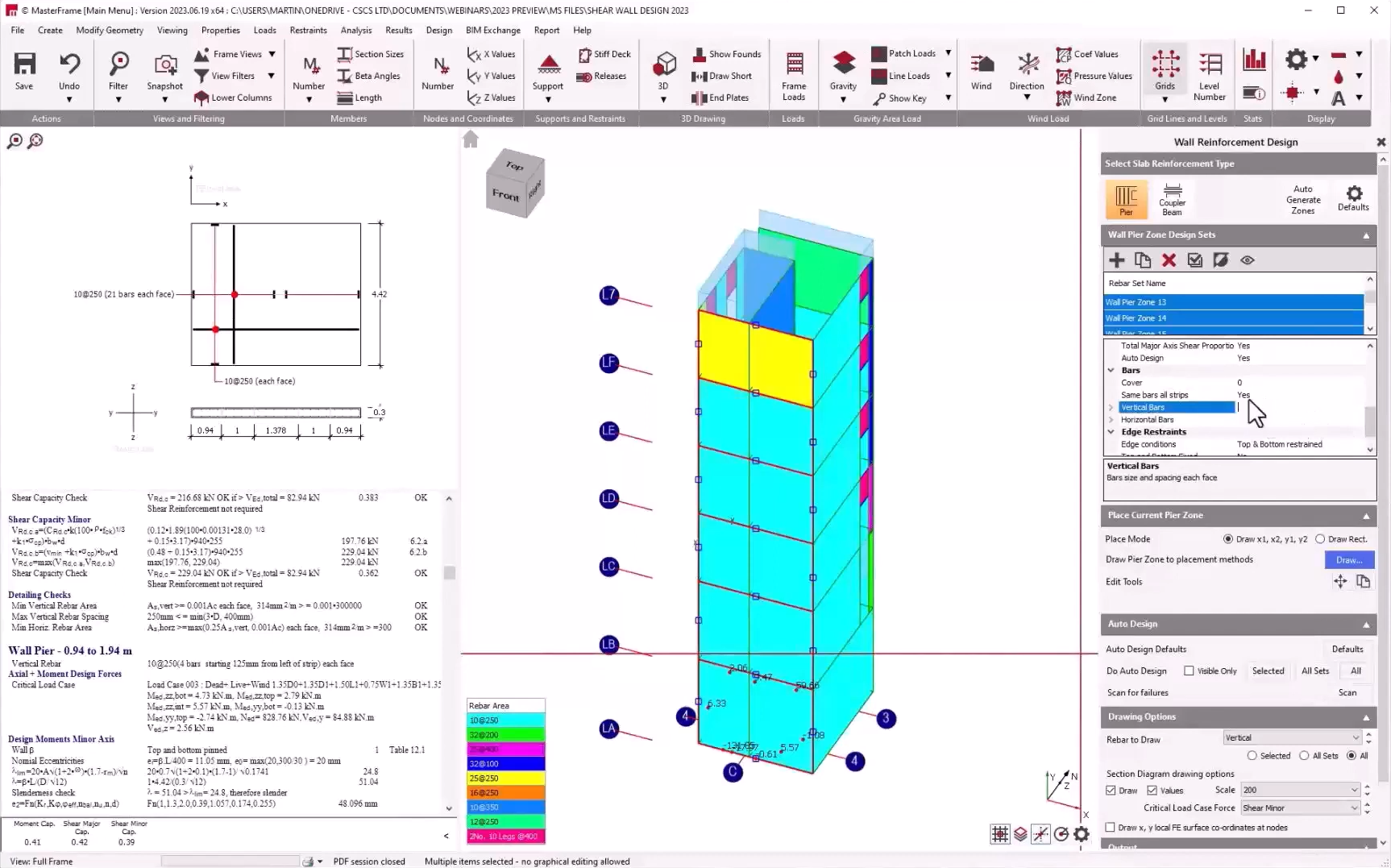
Wall Pier Reinforcement Design
The Wall Design module allows for sub-dividing a vertical wall panel known as a 'Pier', to a series of column-like strips to help get an accurate design for each based on the various applied stresses and forces (axial, bending and shear), allowing the user a great amount of control over the 'Design Methodology' used here.

Wall Coupling Beam Design
Beams which span between the Wall 'Piers' above and below openings are typically classed as 'Coupling Beams'. These transfer loads and moments and can be designed within the software as a standard beam design, or as a 'Strut and Tie' check.

Pier and Coupler Beam Auto-Generation and 'Design Sets'
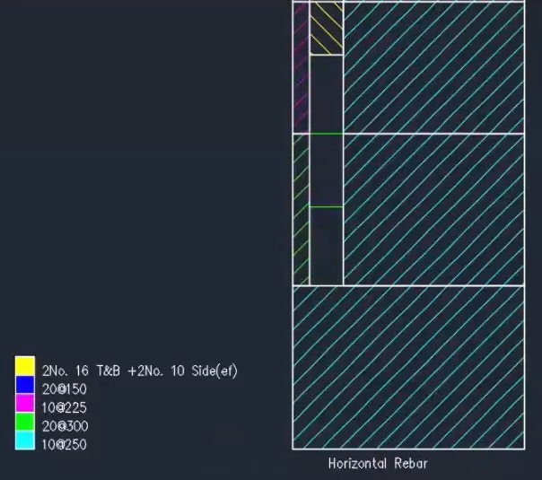
For the management of your design, MasterSeries can easily auto-select and define each of the wall 'Pier' and 'Coupler Beams' depending on their geometric configuration. The 'Auto-Design' feature then allows for the specification of reinforcement for each individual pier or beam.
Using the Multi-Select Feature, MasterSeries allows for the quick rationalisation of the different elements, to define some commonality for the specification of reinforcement across different panels and beams.
MasterKey: Concrete Slab Design also provides facilities to fully calculate deflections for concrete slabs.
The 'Slab Deflection and Crack Control' element of the Concrete Slab Design Module, carries out an iterative non-linear analysis that allows us to get a more accurate deflection than the equivalent linear analysis primarily used for determining ULS moments and design.
This non-linear analysis accounts for many varying factors through different stages of the early life of the slab, taking into account the concrete properties, its strength over time as well as the different loadings applied onto the slab to determine the calculation of the deflection of the structure.
Long-Term Deflection Calculation
- Non-linear analysis
- Taking account of applied reinforcement
- Including cracking, creep, shrinkage and load event sequencing
")
Deflection Check Lines
- Multiple deflection criteria
- Check lines between any two points (typically between support locations or cantilever support to free end)
- Differential deflection between two times

Crack Width Calculation
- Includes the effects of in-plane axial forces (membrane forces)
- Cracking width given on two orthogonal (or rebar) directions

Design to:
- EuroCode 2 - Includes default, UK Nationally Determined Parameter. Open system for user definition of other country NDP's
- Concrete Shear Walls currently only design to EC2
- South African SABS 0100
- BS 8110
You can instantly switch between design codes to compare results.
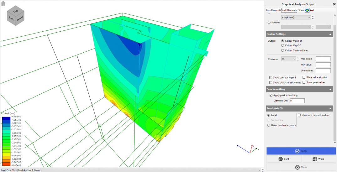
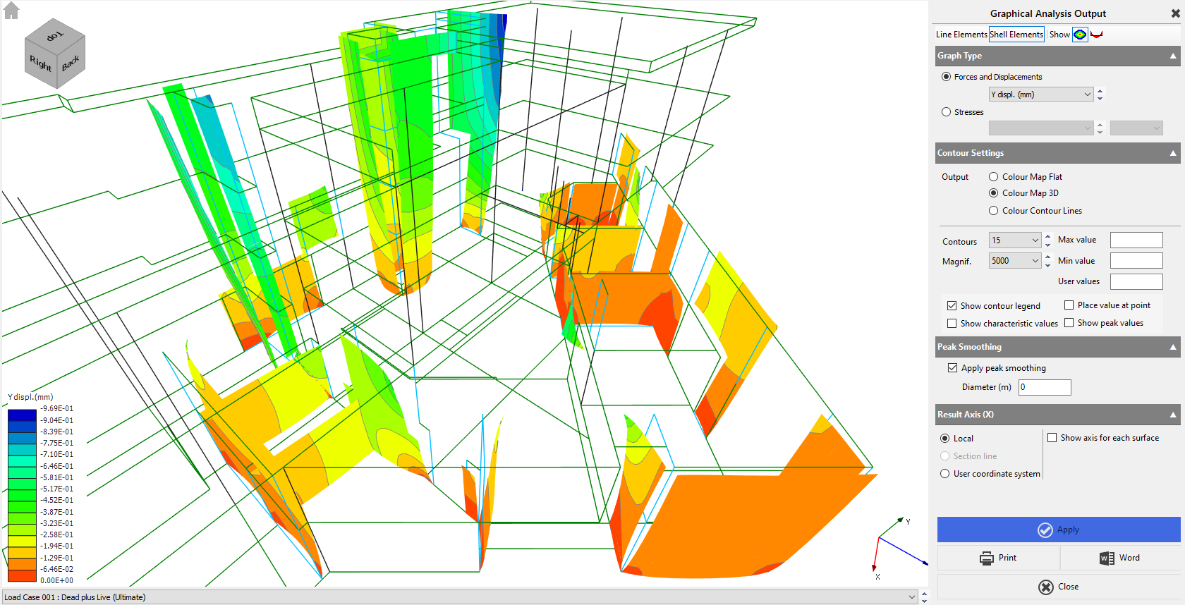
MasterKey: Concrete Slab and Wall Design returns a wide range of analysis outputs which helps the engineer to identify "hot spots" for reinforcing design.
The detailed results with graphics can be included in a report or just simply exported to MS Word. The reinforcement drawings with appropriate keys can be exported into AutoCAD DXF or DWG files for further detailing.

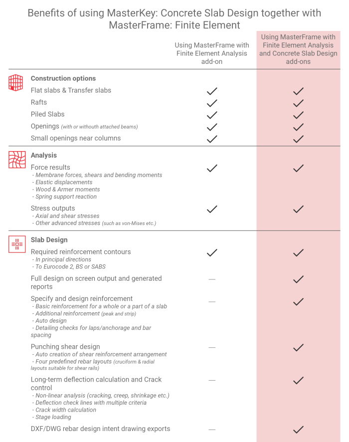
Requires MasterFrame Finite Element Analysis
Optional component. Requires MasterFrame Finite Element Analysis
Not included. Can be added
With MasterFrame Finite Element Analysis
The ultimate 3D building design solution for all multi-material building projects.
MasterFrame Finite Element Analysis FEA module combines the power of MasterFrame with the Finite Element Analysis method to significantly expand your analysis and design capabilities