MasterSeries Blog
How to model and calculate the effect of bolt slip
Using standard bolted connections in a truss, the actual deflection may well be significantly greater than the original analysed frame deflection, due to bolt slip. How can we take into account the effect of the bolt slip in the calculation model?
This month the NSC (Nov/Dec 19) technical paper discusses some of the issues of bolt slip in trusses. In our blog post we will show you, how you can take into account the effect of bolt slip in the calculation and predict the actual deflection of a truss.
In MasterFrame, using the Frame Generator function, almost any geometry of truss can be modelled with just some simple selections and clicks.

Following the conclusion of the technical paper, we would like to model and calculate the effect of bolt slip. In addition to the general loadings, we need to apply a change of length to the affected members.
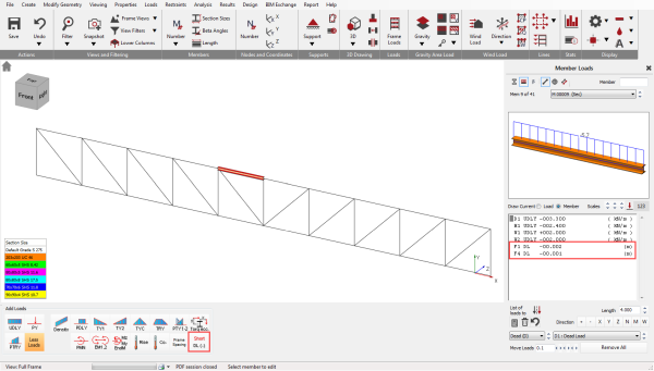
In MasterFrame, change in length is applied as a member loading (Short DL).
Member shortening (or lengthening) can be added to any members on a general bases to apply to all load combinations or using one of the specific load groups we can specify the length change case-by-case.
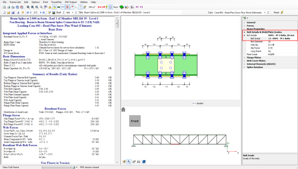
Using preloaded (HSFG) bolts, you can remove the connection slip at either the serviceability limit state or the ultimate limit state.
In MasterSeries Connection Design software, both normal (Category A, EN 1993-1-8) and preloaded (Category B and C) bolts can be used during the connection design.
Example
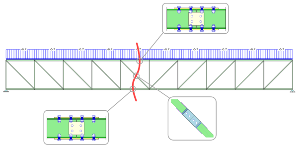
In the following example, we will show how the deflection results change when using standard bolted splice connection in the chords and the diagonal around the mid-span. The other parts of the truss are shop-welded.
We have a 40m span ‘N’ truss. The loading represents the dominant Dead + Snow + Wind load combination in SLS.
We ran the analysis for two model variations:
- Model without any connection slip
- Applying 2 mm lengthening in the tension tensioned chord and diagonal and 2 mm shortening in the compressed chord in the mid-span. It assumes that the members are bolted with 2 mm clearance holes and 1 mm slip can occur in all holes simultaneously at each member ends.
Comparing the vertical deflections in the mid-span, we see that vertical deflection increases by 22% to 58.4 mm, an extra 10.4 mm of deflection.

MasterSeries: Building Design Suite
The Building Design Suite brings together the core MasterSeries analysis, design and BIM software components to provide the ultimate 3D building design solution for large & medium multi-material building projects.
Explore how MasterSeries can help you design more economical solutions and boost your productivity.
Try it for yourself with a free 14-day trial.

Categories
- About
- Beam Designer
- BIM
- Composite design
- Concrete Design
- Connections
- Dynamic
- Educational
- General
- LCA
- Masonry
- MasterFrame
- Pile Cap
- Portals
- PowerPad
- Retaining wall
- Steel Design
- Webinar
- Wind Analysis