MasterSeries Blog
Transverse reinforcement for composite beams
In composite beams, the longitudinal shear connection between the steel and the concrete parts is provided by shear connectors. But how can we prevent the transferred longitudinal force from the shear connectors from splitting the concrete flange?
The longitudinal shear resistance of the concrete flange must be checked to ensure that the force from the shear connectors can be transferred into the slab. It might require transverse reinforcement.
To determine the longitudinal shear resistance, Eurocode 4 states that the rules of Eurocode 2 for reinforced concrete slabs should be used. The relevant shear failure surfaces determined by the Eurocode 4 are shown below for concrete slabs with sheeting.

The practical solution is to make the studs high enough for type ‘a’ or ‘d’ to govern.
The effective transverse reinforcement for the shear failer surfaces above is the following:

Both top and bottom reinforcement play an essential role in preventing splitting of the concrete.
The decking may also be part of the transverse reinforcement, but needs to be adequately anchored and the ribs of the decking must run perpendicular to the beam.
Using the model given in the Eurocode 2 in which the flange is considered to act as a system of compressive struts combined with a system of ties from the transverse reinforcement, the design shear strength of the concrete flange can be determined with the following expression:
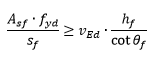
where
Asf is the area of effective reinforcement for the failure surfaces
sf is the spacing of the reinforcement bars
vEd is the design value of the transverse shear force
hf is the depth of the flange
θf is the angle of dispersion of the force from the shear connector
Position of the mesh
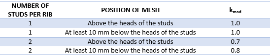
However, the transverse reinforcement may affect the resistance of the shear studs as well.
As reported in NCCI PN001a-GB test results, the resistance for shear studs in transverse trapezoidal sheeting is not only depended on the number of the studs but on the position of the mesh as well.

They have introduced a reduction factor (kmod) additional to the solid slab reduction factor (kt).
Click HERE to read more about calculating the design resistance of a headed shear stud in our previous blog post.
MasterSeries Composite Design
MasterSeries Composite Structure Design solutions provide state-of-the-art, fully automated structural design for traditional (solid slab or metal deck profile) and slim-floor steel-concrete composite floors to Eurocode and British Standard.
Explore how MasterSeries can help you design more economical solutions and boost your productivity.
Try it for yourself with a free 14-day trial.

Categories
- About
- Beam Designer
- BIM
- Composite design
- Concrete Design
- Connections
- Dynamic
- Educational
- General
- LCA
- Masonry
- MasterFrame
- Pile Cap
- Portals
- PowerPad
- Retaining wall
- Steel Design
- Webinar
- Wind Analysis