MasterSeries Blog
Structural modelling with FE surfaces
Finite element analysis is an extremely useful tool to analyse structures that are too complex for regular analytical solutions.
However, when modelling with finite elements, the question of how to connect and combine different structural elements, sooner or later come up. In this blog post, we are going to review the different types of releases and restraints that we can use.
Member end-releases
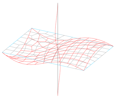
When combining FE surfaces with 1D structural members, member end-releases can be used to limit the internal forces that are transmitted from the members to the FE surfaces.
For example, it can be used to model how the columns connect to a slab.
In the first picture, the columns are connected rigidly to the slab, thus the bending moment is transferred from the slab to the columns.
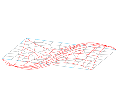
In the second picture, the columns are pinned above & below the slab, thus only axial force is transmitted from the slab to the columns.
Line releases
By default, when FE surfaces touch each other, the connection is continuous between them.
Using line releases, we can free up particular degrees of freedom from the transfer. Line releases can be placed on the perimeter of a surface.
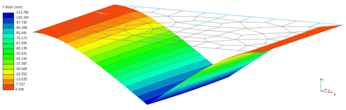
The example below shows a line hinge between two surfaces. Only shear and axial forces are transferred from each other. The release is only applied to one of the two surfaces.
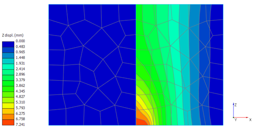
However, with line release, it is possible to separate shell elements from each other and transfer only certain forces as well.
In the picture below, the two surfaces are connected to each other apart from the shortest direction (z) in which the two surfaces can move independently.
Supports
Supports are used to transfer the loading from the structure to the foundations. Any of the nodes of an FE surface can be used to place support. Support (except surface support) can be defined to act in each of the six degrees of freedom (3 displacements and 3 rotations).
Generally, there are three types of supports: nodal, line and surface support.
Nodal support: blocks at least one degree of freedom of the node. Can be used to model a pile, column etc.
Line support: sets the boundary conditions of the nodes along the line. A range of line restraint/support conditions can be applied to FE surfaces. Line support can be used to model the supporting effect of a wall etc.
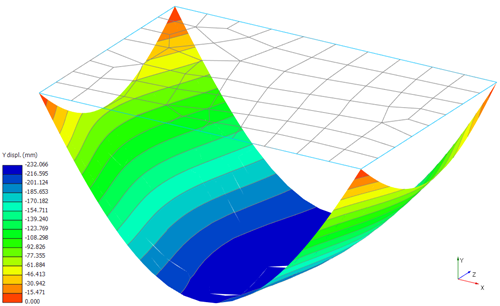
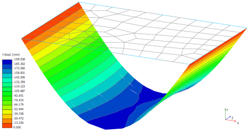
The first example shows a pinned slab, while the second one a fixed slab.
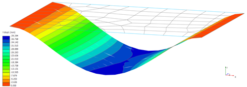
Surface support:
In MasterFrame, in the case of a horizontal FE surface, an area-based linearly elastic, full surface area vertical spring support can also be defined. The option allows for the definition of a vertical spring to be applied over the area of an FE surface. The spring can be set as either compression/tension or compression only.
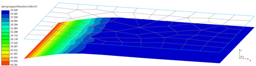
Surface support can be used to model a raft foundation.
Explore how MasterSeries can help you design more economical solutions and boost your productivity.
Try it for yourself with a free 14-day trial.

Categories
- About
- Beam Designer
- BIM
- Composite design
- Concrete Design
- Connections
- Dynamic
- Educational
- General
- LCA
- Masonry
- MasterFrame
- Pile Cap
- Portals
- PowerPad
- Retaining wall
- Steel Design
- Webinar
- Wind Analysis