MasterSeries Blog
Deflection of cantilevers in structural design software versus standard formulae
An area of design that frequently leads to confusion is the calculated value of deflection for cantilevers that results from structural design software. Frequently, the deflection used is higher than obtained by doing a manual check on the deflection by utilizing standard deflection formulae taken from reference texts.
Deriving a standard cantilever formula and the effect of the boundary conditions
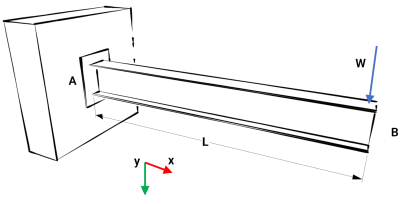
Consider the cantilever shown below, with a point load W, applied at the free end B, with fixed support at end A. The stiffness of the beam is assumed to be EI, and the beam self-weight is taken to be negligible, i.e., self-weight is ignored.
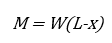
The bending moment M taken at a section along the length of the beam is given by
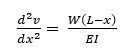
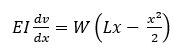
Substituting for M, we then have the 2nd order differential equation
Since this is a 2nd order differential equation, solving for the deflection v will require the determination of two constants of integration which will be derived from the boundary conditions. Integrating equation (2) with respect to x gives
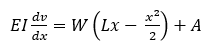
where A is a constant of integration. From the boundary condition dv/dx=0 where x=0, that is at the built-in end, that is the slope of the beam is zero, which gives A=0, and so
Integrating again gives
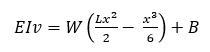
where B is a constant of integration determined by the boundary condition v=0 where x=0, that is the deflection of the beam at the built-in end is zero. The boundary condition gives B=0, and so we have
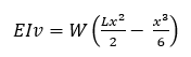
Rearranging then gives the equation for the deflection of the cantilever beam
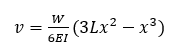
The maximum deflection occurs at the free end of the cantilever, where x=L. Substituting for x then gives
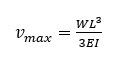
While many reference texts often give the deflection formula for a cantilever with a point load applied at any location along the beam, using the standard formula with a point load at the free end of the beam simplifies to give the above equation.
One of the key steps in the above procedure is to define the boundary conditions that enable the integration constants to be determined. The condition v=0 defines the condition that the deflection of the beam at the fixed support is zero, which reflects the fact that at the support, the beam is fixed in position. The other condition associated with the fixed support is the fact that the rotation of the beam is restrained at the fixed end. This means that, at the fixed support, the beam remains horizontal, which gives the boundary condition dv/dx = 0 where x=0.
It is the condition of no rotation of the beam at the fixed support that is most relevant when checking the deflections of a cantilever in a frame analysis against standard formulae. While the formulae above is based on a cantilever with a point load on the end of the member, the same issue occurs regardless of how the member is loaded and the same process given above can be carried out for a variety of loading arrangements. In each case, the solution depends on the support conditions.
Using structural design software
The fixed support condition discussed above can be achieved in structural design software by using fixed nodal support. This will restrain any members connected to that node both positionally (dx, dy and dz restraint) and rotationally (θx, θy and θz restraint). However, in a frame analysis, it is much more common for cantilever members to be connected to other elements of the structure. When this is the case, the supported end of the cantilever is now dependent upon the stiffnesses of the other frame elements it is connected to. While the cantilever is fixed to the supporting members assuming fully moment transfer, the stiffness of the supporting members mean that the restraint is now dependent on the stiffness of the supporting frame elements. Rather than acting like a fixed nodal restraint, the supported end will now act like a spring support. In general, this is less significant for the positional restraint of the supported end of the cantilever, but the rotational stiffness can have a significant impact, allowing rotation of the cantilever. A rotation of the support end will lead to a corresponding deflection at the free end, a deflection which occurs in addition to the deflection of the member due to the loading.
For cantilever members which are dependent upon other structural elements for support, the rotational stiffness of the supported end is accounted for in the frame analysis, but the resulting additional deflection is not taken into account with standard deflection formulae such as that derived above. Therefore, it is likely that the deflection of the unsupported end of the cantilever will be greater than the value given when using a standard formula and account needs to be taken of the effect of the rotation of the support.
Worked Example using MasterFrame
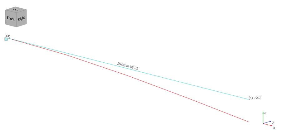
Consider a cantilever beam of length 2.0 m and steel section 254x146UB31 with Iy = 4410 cm4 and Youngs’ modulus E = 210000 N/mm2. The load is a point load of 10 kN (dead) applied to the free end of the cantilever. For the purpose of the calculations, the self-weight of the steel elements has been ignored.
Two different support conditions are modelled:
- Case 1: the cantilever is supported by a fixed nodal support

- Case 2: the cantilever is supported by a 3.5 m long 203x203UC46 section. The column has a fixed nodal support at its base while at the head of the column, a nodal support restraining the node in the dx and dz directions has been used to prevent lateral sway of the column and beam. In this arrangement, the rotation of the supported end of the cantilever is dependent on the bending stiffness of the column.

Case 1 – Fixed support
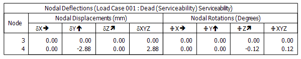
Examining the Deflected shape + geometry results, the MasterFrame gives a deflection of 2.9mm for the vertical (y-axis) deflection of the cantilever.
The tabular results gives the deflection of node N4 as 2.88mm. The difference is due to rounding in the graphical results area.
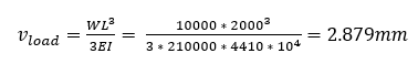
Checking this using the standard deflection formula (8) we then have:
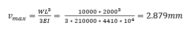
The results from the MasterFrame analysis are in agreement with the deflection obtained from the derived deflection formula. It can be seen from the tabular results that the deflections and rotations of node N1 are all zero so the support condition in the model matches with the support conditions used in the derivation of the deflection formula (8).
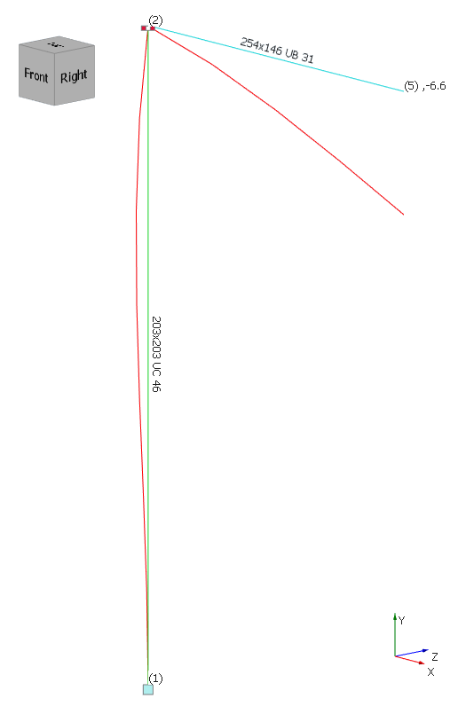
Case 2 – Cantilever supported by a column
Using the Deflected shape + geometry results to examine the vertical (y-axis) deflection of the cantilever, MasterFrame gives a deflection of 6.6mm. The deflected shape of the structure is shown below and it can be seen that in addition to deflection of the cantilever due to the point load applied to the free end, the column is also undergoing some deformation.
The tabular results area gives the deflection of node N5 as 6.55mm. The difference in the deflection given here versus the results from the graphical results is due to rounding in the graphical results area.
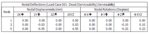
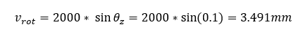
In addition to the deflection at node N5, the tabular results also indicate that node N2 is also undergoing a (small) vertical deflection due to the elastic shortening of the column under axial load and a rotation about the z-axis of 0.1 degrees.
The additional deflection at the free end of the cantilever due to the rotation is:
and as before the deflection of the free end of the cantilever due to the load is
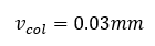
and the deflection due to the column shortening is
Hence the calculated total deflection of the free end of the cantilever is
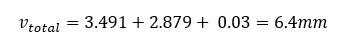
This compares well with the results given in MasterFrame, with minor differences due to numerical rounding in the results.
Conclusion
When checking the results of the analysis of a model involving cantilever members, it is important to recognise the importance of the support conditions, in particular, the effect that rotations of the support can have on the overall deflection of the members. It is important to recognise that the standard formulae for deflection are all dependent on the boundary conditions which, in the case of structural elements, are given by the support conditions.
The issue is not limited to cantilever members since continuous members connected at a node will also be dependent on the rotation at the connections when assessing deflections.
Did you like this post? Don't miss similar topics!

Categories
- About
- Beam Designer
- BIM
- Composite design
- Concrete Design
- Connections
- Dynamic
- Educational
- General
- LCA
- Masonry
- MasterFrame
- Pile Cap
- Portals
- PowerPad
- Retaining wall
- Steel Design
- Webinar
- Wind Analysis