MasterSeries Blog
Pinned or Fixed? The Truth About Column Base Behaviour
In most structural analysis models, column bases are typically defined with a single click as either pinned or fixed.
That choice often feels routine — a necessary assumption made early so the model can run. However, in practice, column base connections are among the most complex and least idealised elements in a steel structure. They sit at the interface between steelwork, foundations, construction tolerances, and real-world behaviour, and they rarely behave in a purely pinned or fully fixed manner.
This gap between idealised assumptions and actual behaviour is where design risks can quietly arise.
The Comfort of Simplified Boundary Conditions
Global analysis relies on idealised boundary conditions. Without them, the structure cannot be analysed efficiently or consistently.
For column bases, this usually means one of two assumptions:
- Pinned, providing no moment resistance
- Fixed, providing full rotational restraint
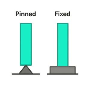
These assumptions are useful, but they are also extremes. In reality, column bases almost never sit at either end of this spectrum.
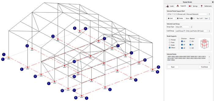
In reality, column bases exhibit partial stiffness, which varies depending on:
- Baseplate thickness and geometry
- Anchor size, number, and arrangement
- Concrete strength and cracking behaviour
- Grout condition and installation quality
- Axial force level and moment direction
Yet these factors are rarely reflected in global models. Where a more realistic representation is needed, semi-rigid behaviour is commonly modelled using rotational springs, allowing the support stiffness assumed in analysis to better reflect the behaviour of the actual base detail.
What Actually Happens at the Base
Unlike many other connections, a column base must simultaneously deal with:
- Axial load (often high and variable)
- Shear
- Bending moment
- Uplift or load reversal
- Construction and erection stages (temporary conditions)
These actions do not act independently. They interact, redistribute, and change over time.
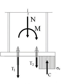
A useful way to understand this is to look at how the load path changes once moment is introduced. Under pure axial compression, the base can behave in a relatively straightforward way, with concrete bearing beneath the plate and plate thickness driven by compression and bending in the plate itself. Once moment is added, that simple picture changes. A compression zone forms on one side of the base plate, tension develops in the anchors on the other side, and the plate bends between the two regions. In other words, the base is no longer just “supporting the column” — it is actively redistributing forces between steel and concrete. The result is that column bases often experience demand that is not obvious from reaction forces alone.
Where Problems Typically Appear
Issues with column bases rarely present themselves as immediate failure. Instead, they show up as:
- Excessive movement or rotation
- Unexpected cracking of concrete
- Anchor bolt distress
- Fit-up problems on site
By the time these issues are identified, design flexibility is often limited, and changes become expensive.
One of the biggest risks is not simply under design - it is a mismatch. A base may be modelled as semi-rigid, but then detailed as a much stiffer connection in practice. Or it may be treated as pinned in the frame model, while the actual base detail still develops meaningful rotational restraint. In both cases, the structure behaves differently from the way it was analysed.
Responsibility Beyond the Analysis Model
Column bases sit in a grey area between disciplines and responsibilities. They involve steelwork, foundations, and construction sequencing. It is easy to assume that detailed behaviour will be resolved elsewhere.
But assumptions made in global analysis influence:
- Member sizes
- Stability checks
- Force paths
- Detailing constraints
If those assumptions are inconsistent with the base's real behaviour, risk is simply transferred downstream. Understanding column base behaviour does not mean abandoning simplified models. It means knowing when those simplifications are no longer good enough.
Where Column Bases Are Really Tested
Column base design rarely becomes challenging for just one reason. As soon as moment or horizontal force increase, several checks start working together.
Anchors are often where the real pressure shows up. Once tension from moment and shear from horizontal load begin to build, the design has to consider more than simple bolt strength. Pull-out, concrete cone failure, edge shear, and pry-out can all become governing checks, especially where anchors are closely spaced or concrete conditions are restrictive.
As demand rises, the detailing often has to evolve with it. Increased moment can quickly turn plate bending into a governing issue, and stiffeners may be needed to improve performance. Even then, solving one weakness can shift the demand elsewhere, such as into the column flange or the supporting concrete.
That is why column base design is rarely about a single check. It is about understanding how the whole connection responds as forces increase and making sure the detail develops with the demand. Beyond local design checks, column base behaviour also has a direct influence on global structural response.
Why Base Stiffness Matters in Global Analysis
Although the Connection Design module does not currently calculate and automatically transfer base plate rotational stiffness into the frame model, MasterSeries allows engineers to define column base fixities and analyse structures using semi-rigid supports. This is not just a theoretical refinement. It can significantly influence structural behaviour.
As demonstrated in our earlier article, “Utilising the stiffness of nominally pinned bases in frame design” (MasterSeries Blog, 2019), even introducing a modest 20% base fixity resulted in:
- Nearly 40% reduction in horizontal displacement
- Less than 5% change in mid-span deflection
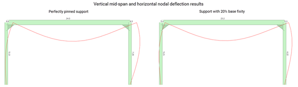
This illustrates an important engineering principle:
Base stiffness can have a major impact on frame sway behaviour, while having relatively little influence on vertical bending response.
By combining detailed base plate design checks with realistic semi-rigid modelling assumptions, engineers can better align local connection behaviour with global frame performance, leading to more accurate and efficient designs.
Conclusion
Column bases may appear simple in analysis models, but their real behaviour is anything but.
By understanding how stiffness, load interaction, and detailing influence performance, engineers can move beyond idealised assumptions and design structures that better reflect reality.
Even small changes in how base behaviour is considered — such as introducing semi-rigid assumptions — can lead to significantly improved structural performance and more efficient design.
See It in Practice
Take your structural design further with the MasterSeries Building Design Suite — our comprehensive frame analysis and design solution with an integrated Connection Design module.
Design and check a wide range of connections, including:
- Moment connections
- Simple connections
- Bracing connections
Using the fully integrated mode, connection geometry and forces are transferred directly from the 3D structural model, creating a seamless workflow between global analysis and detailed connection design.
- You can request a free trial and explore the software yourself:
https://www.masterseries.com/f... - Or book a live demo and see the program in action with one of our engineers:
https://www.masterseries.com/d...
Categories
- About
- Beam Designer
- BIM
- Composite design
- Concrete Design
- Connections
- Dynamic
- Educational
- General
- LCA
- Masonry
- MasterFrame
- Pile Cap
- Portals
- PowerPad
- Retaining wall
- Steel Design
- Webinar
- Wind Analysis