MasterSeries Blog
Shear Connection in Composite Beams: When Does Composite Action Really Occur?
Composite beams are widely used in steel buildings because they allow the steel beam and concrete slab to work together efficiently. When properly connected, this composite action significantly increases both the strength and stiffness of the structural member, often allowing longer spans or reduced floor depths.
However, composite action does not occur automatically. Simply placing a concrete slab on top of a steel beam does not make the two elements act together. For this interaction to develop, forces must be transferred between the steel and concrete. This is achieved through shear connection.
Understanding how shear connection works — and how it is designed — is essential for composite beam design.
Non-Composite vs Composite Behaviour
In conventional construction, if a concrete slab simply rests on top of a steel beam, the two components can slip freely relative to each other when the beam bends.
In this case:
- The steel beam resists the bending forces
- The concrete slab acts mainly as dead load
The beam therefore behaves as a non-composite steel beam, and the structural contribution of the slab is minimal.
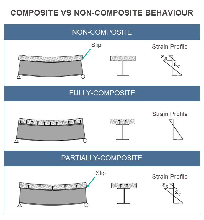
To enable composite behaviour, the steel beam and concrete slab must be connected so that slip between them is prevented or controlled. When this connection is provided, the two components deform together and act as a single structural member.
This interaction is known as shear connection.
How Shear Connection Works
The connection between the steel beam and the concrete slab is usually provided by headed shear studs welded to the top flange of the steel beam.
When the beam bends under load, longitudinal shear forces develop along the interface between the steel and concrete. These forces arise because the slab is in compression while the steel beam carries tension.

The shear connectors transfer these longitudinal shear forces between the two components and prevent excessive slip.
By enabling this force transfer:
- The concrete slab carries compression
- The steel beam carries tension
This allows the composite section to develop its full bending resistance and stiffness.
In addition to longitudinal shear, shear studs may also be subjected to tensile forces, particularly in certain loading or detailing situations.
Design of Shear Studs to Eurocode 4
The design of shear connectors in composite beams is covered by Eurocode 4.
For a headed shear stud embedded in a solid concrete slab, the design resistance is determined from two possible failure mechanisms:
- failure of the steel stud
- failure of the surrounding concrete
The design resistance of the stud is governed by the smaller of these two values.
The Eurocode 4 design expression for the resistance of a headed shear stud is shown below.
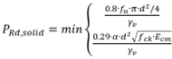
The calculation depends on several parameters, including:
- fu – ultimate tensile strength of the stud
- d – diameter of the stud shank
- fck – characteristic cylinder strength of the concrete
- Ecm – secant elastic modulus of the concrete
When studs are used within profiled steel decking, the resistance must be reduced using a reduction factor.
This reduction factor depends on:
- orientation of the decking ribs relative to the beam
- geometry of the deck profile
- thickness of the steel sheeting
These effects are accounted for in the design rules of Eurocode 4.
Full and Partial Shear Connection
In a composite beam, shear connectors must transfer the longitudinal shear forces that develop between the steel beam and the concrete slab as the beam bends.
According to Eurocode 4, the maximum longitudinal shear force that needs to be transferred is the smaller of:
- the compressive force that would cause crushing of the concrete slab, or
- the tensile force that would cause yielding of the steel section
This force represents the maximum interaction that can develop between the steel beam and the concrete.
Depending on the amount of shear connection provided, the beam may develop either full or partial shear connection.
Full Shear Connection
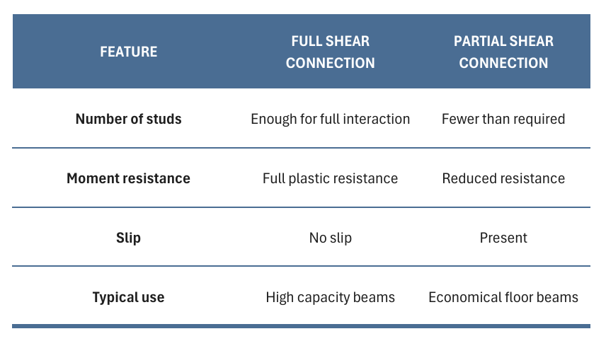
Full shear connection occurs when sufficient shear connectors are provided to transfer the maximum longitudinal shear force between the steel and concrete.
In this case, the composite beam can develop the full plastic moment resistance of the composite section.
Providing additional studs beyond this point does not increase the bending capacity.
Partial Shear Connection
In many practical situations, it may not be possible or economical to provide the number of studs required for full shear connection.
This can be due to factors such as:
- deck rib spacing
- construction constraints
- economic optimisation
When fewer connectors are provided, the beam develops partial shear connection.
The beam still behaves compositely, but the bending resistance is limited by the amount of shear force that can be transferred between the steel beam and the slab.
Partial shear connection is very common in real structures and often provides a more efficient design solution.
Slip in Partial Shear Connection
When partial shear connection is used, the deformation of the shear connectors allows limited slip between the steel beam and the concrete slab.
This slip varies along the beam:
- it is zero at the location of the maximum bending moment
- it increases towards the supports
This behaviour must be taken into account when determining the bending resistance of the composite section.
The degree of shear connection is typically defined as the ratio between:
- the number of connectors provided, and
- the number required for full shear connection
Determining the Number of Shear Studs
Once the required longitudinal shear force has been established, the number of shear connectors required can be determined from the design resistance of an individual stud.
The required number of connectors is obtained by dividing the total longitudinal shear force that must be transferred by the design resistance of a single shear stud, calculated according to Eurocode 4.
This provides the number of connectors required to achieve full shear connection.
If fewer studs are provided, the beam will develop partial shear connection, and the bending resistance of the composite section must be determined accordingly.
In practice, the final number of studs is often influenced by additional factors such as deck geometry, construction practicality, and economic optimisation.
Typical Shear Stud Spacing in Practice
While the required number of shear studs is determined from the longitudinal shear force, their spacing along the beam must also satisfy practical and code-based requirements.
In composite beams, the demand for shear transfer is not uniform along the span. Longitudinal shear forces are generally highest near the supports, where the rate of change of bending moment is greatest, and reduce toward the region of maximum bending moment.
Because of this behaviour, shear connectors are often distributed along the beam so that sufficient shear transfer capacity is available where it is most needed.
Design standards such as Eurocode 4 also specify limits on stud spacing to ensure reliable force transfer and proper composite behaviour. These limits typically control:
- maximum spacing between studs along the beam
- minimum spacing between studs
- distance from beam ends or supports
In many practical floor systems, stud spacing is also influenced by the profiled steel decking, since studs are typically placed within the deck ribs.
As a result, the final stud arrangement often reflects a combination of:
- required shear resistance
- deck geometry
- construction practicality
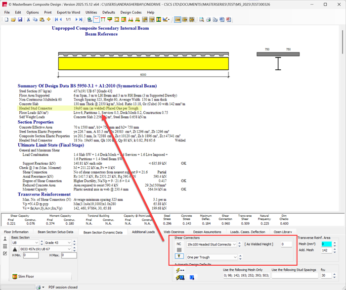
Balancing these factors allows engineers to achieve an efficient composite beam design while ensuring that the required shear transfer is safely provided.
Why Shear Connection Is Critical
Without shear connection, the concrete slab would contribute very little to the beam’s bending resistance. The steel section would effectively carry the structural forces alone.
By enabling force transfer between steel and concrete, shear connectors allow the beam and slab to act together as a single structural system.
This interaction leads to:
- significantly higher bending capacity
- much greater stiffness
- more efficient use of materials
It is this mechanism that makes composite beams one of the most effective structural solutions in modern building construction.
Conclusion
Composite action only occurs when sufficient shear connection allows forces to transfer between the steel beam and concrete slab.
Headed shear studs provide this connection by resisting longitudinal shear forces and limiting slip at the interface between the two materials.
By enabling the slab and beam to act together, shear connectors allow composite beams to achieve greater strength, higher stiffness, and more efficient structural performance.
Understanding how shear connection works — and how it is designed according to Eurocode 4 — is therefore fundamental to the design of composite floor systems.
Try Composite Beam Design with MasterBeam
Designing composite beams can involve many interacting checks — from load sharing and shear connection design to deflection control and construction stage behaviour. MasterBeam: Composite Design simplifies this process with a powerful yet highly intuitive design environment built specifically for structural engineers.
The program allows you to quickly design primary, secondary, and mixed primary-secondary composite beams, with or without web openings, while automatically handling the complex interaction between the steel section, concrete slab, and shear connectors.
Flexible workflows
- Standalone design tool – ideal for quick composite beam design and optimisation.
- Integrated Building Design workflow – use it as part of the Building Design Suite to design composite floors directly within a complete 3D structural model.
Whether you are designing a single beam or an entire floor system, MasterBeam: Composite Design streamlines calculations, automates code checks, and presents clear engineering results.
See it in action
- Learn more: https://www.masterseries.com/p...
- Request a free trial: https://www.masterseries.com/f...
- Book a live demo with one of our engineers: https://www.masterseries.com/d...
Start exploring how MasterBeam: Composite Design can simplify and accelerate your composite beam design workflow.
Categories
- About
- Beam Designer
- BIM
- Composite design
- Concrete Design
- Connections
- Dynamic
- Educational
- General
- LCA
- Masonry
- MasterFrame
- Pile Cap
- Portals
- PowerPad
- Retaining wall
- Steel Design
- Webinar
- Wind Analysis