MasterSeries Blog
How to design web to flange welds in plate girders?
Nearly all plate girders built today are welded. Two flange plates fillet welded to a web plate to form an I-section. But how to design the welds between the flange and web of a plate girder?
The web to flange welds carries the shear stresses which act on planes parallel to the longitudinal axis of the beam.

Designing web to flange welds, the standard formula for calculating the shear stress can be written in terms of shear flow “s” between the web and flange:

where,
The shear flow is the shear force per unit length (kN/m) to be carried by the web to flange welds.
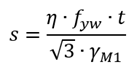
Part 5 of Eurocode 3 (9.3.5) gives a simplified method to calculate the shear flow for designing web to flange welds:

where hw is the depth of the web. For larger values of the weld between flanges and webs should be designed for
Designing the web to flange weld to Eurocode 3
Using the simplified method of the Eurocode 3 (EN 1993-1-8 clause 4.5.3.3), the design resistance of a web and flange weld may be assumed to be adequate if, at every point along its length satisfies the following criteria:
where Fw,Ed is the design value of the weld force per unit length and Fw,Rd is the design weld resistance per unit length.
If we have a fillet weld at each side of the web, then the design value of the weld force is the following:

Independent of the orientation of the weld throat plane to the applied force, the design resistance per unit length Fw,Rd should be determined from

where,

For more details about the web to flange weld design, please read the New Steel Construction Advisory Desk Note AD411 (pdf).
Web to flange weld design using the MasterSeries – New Feature!
The latest update of the integrated steel design module (MasterKey: Steel Design) of the MasterFrame, MasterPort and MasterBeam beam designer introduced a new feature to allows the design of web to flange welds to a plate girder.
When defining a new plate girder, there is a new option to set the web to flange weld size for design.

We can set a specific weld size to check or using the Auto option, we can ask the software to find the appropriate welding size.
In the case of a plate girder, the MasterKey: Steel Design automatically performs the Web to flange Weld Design check and provide the weld size if necessary.

Using specific weld size, partial penetration and hit and miss unit length also can be set.
Explore how MasterSeries can help you design more economical solutions and boost your productivity.
Try it for yourself with a free 14-day trial.

Categories
- About
- Beam Designer
- BIM
- Composite design
- Concrete Design
- Connections
- Dynamic
- Educational
- General
- LCA
- Masonry
- MasterFrame
- Pile Cap
- Portals
- PowerPad
- Retaining wall
- Steel Design
- Webinar
- Wind Analysis